2.72 Elements of Mechanical Design
2.72 - Elements of Mechanical Design is a class at MIT taught by Professor Martin Culpepper that focuses on modeling, design, integration, and best practices for using machine elements such as bearings, bolts, belts, flexures, and gears. The class culminates in a final project where teams of students build a desktop lathe.
Functional Requirements
Our team began by defining functional requirements for our lathe. Our main constraints were that the lathe must be repeatable to 50 microns and we had a budget of $200. We were also provided a motor with a a maximum power of 337 W. Given these parameters, we defined functional requirements for the efficiency, stiffness, temperature sensitivity, and dimensions of the lathe. We further broke down these functional requirements into requirements for each system on the lathe (ex. spindle, carriage, etc.). These system requirements acted as checkpoints to ensure we were on track to meet our overall functional requirements.
Spindle and Cross Slide Design
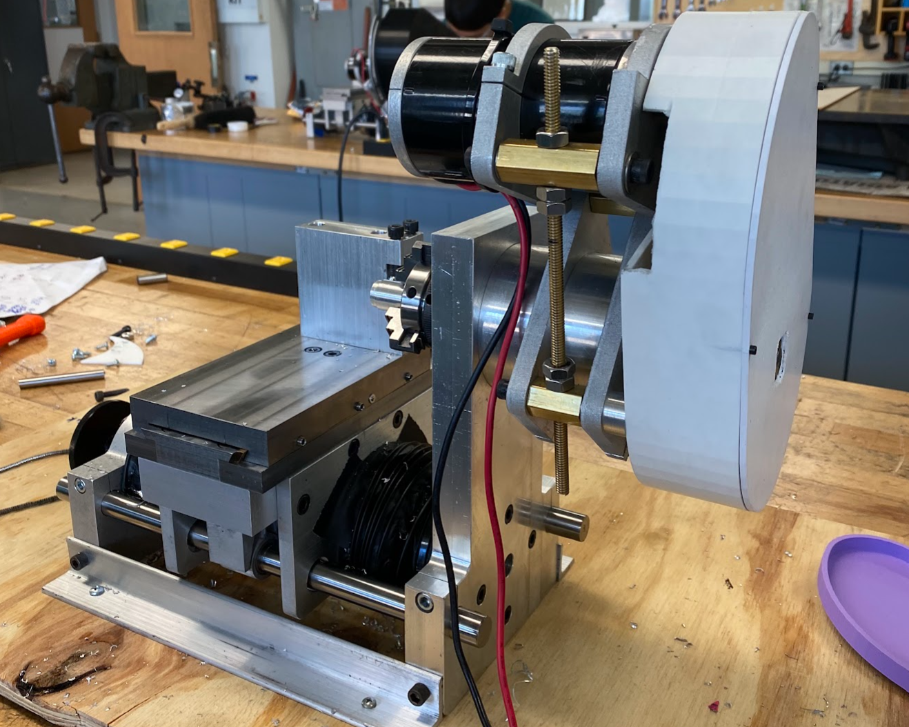
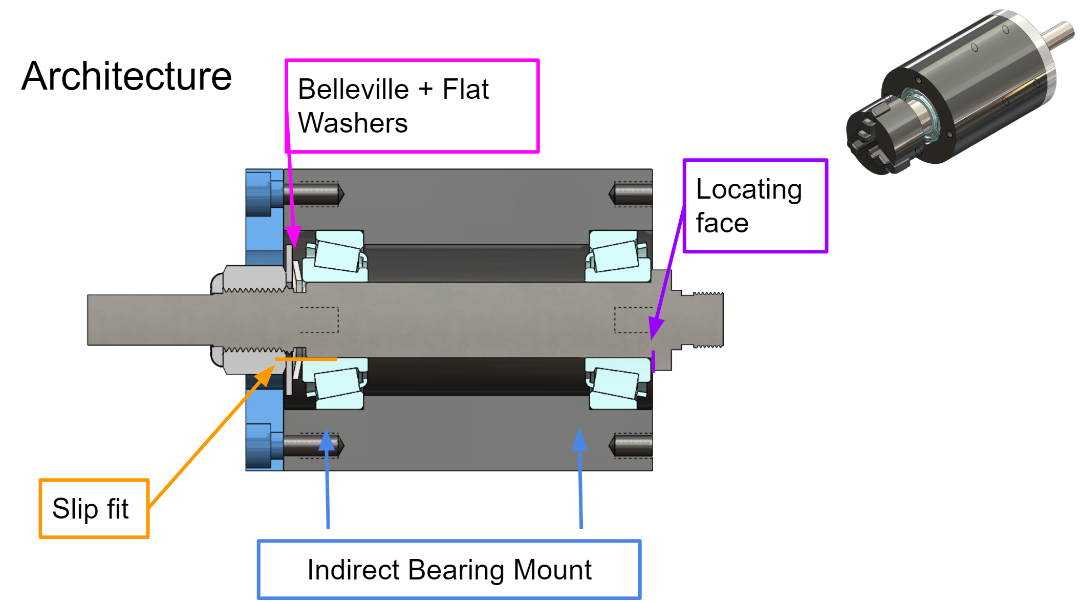
We chose an indirect bearing mount architecture to support the spindle. We had a slip fit between the spindle and bearing in the back and a press fit with the bearing in the front. This allowed for axial thermal expansion of the spindle while constraining the shaft. We applied preload to the bearings with a nut and Belleville washer.
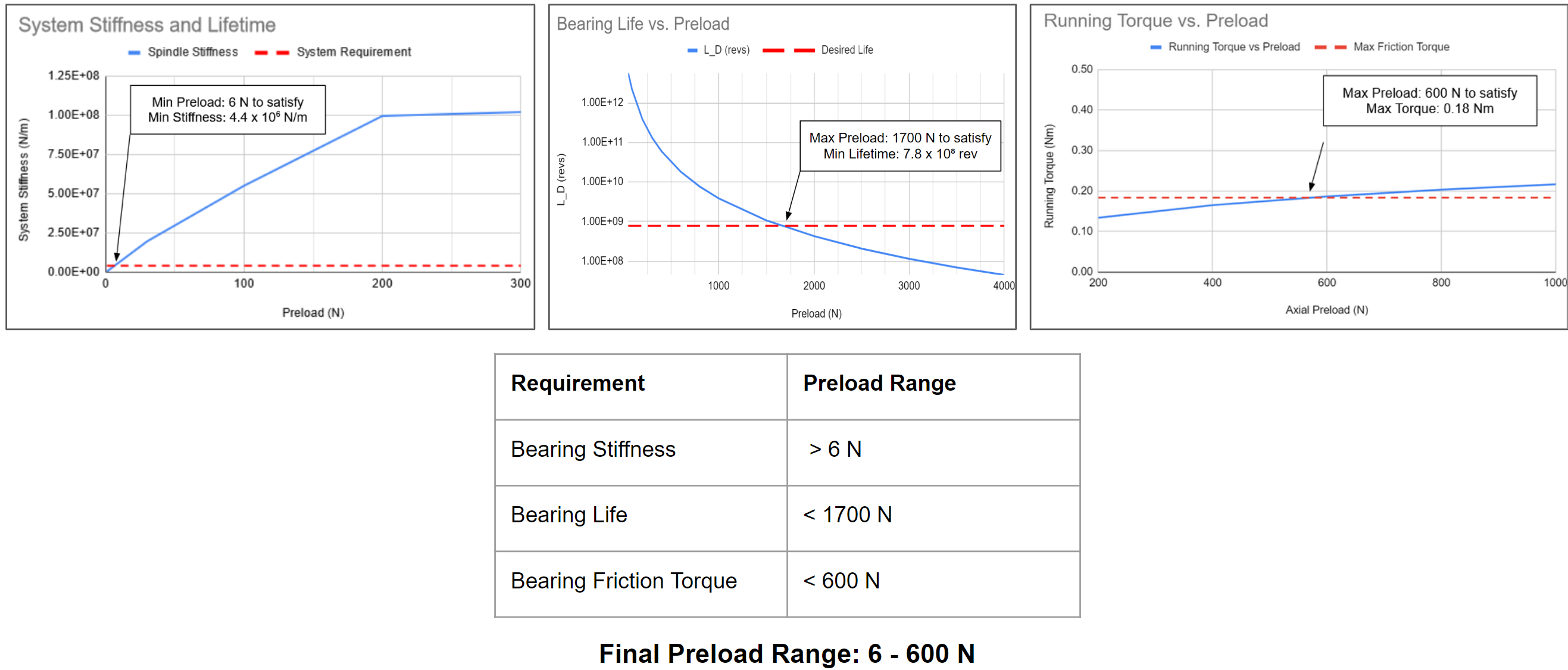
To determine the preload value, I compared its effect on system stiffness, bearing life, and efficiency. Increasing the preload increased the stiffness and decreased the bearing life and efficiency of the lathe. Thus, the minimum preload was limited by our stiffness requirement and the maximum preload was limited by the bearing life and efficiency requirements.
Once we assembled the spindle, we took measurements to verify that it met our functional requirements which it did.
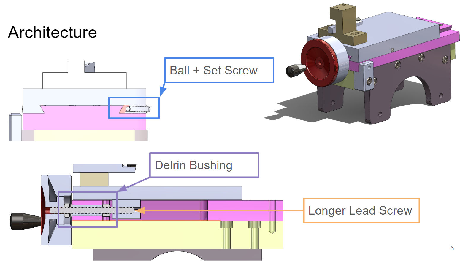
Our cross slide featured a dovetail base actuated by a lead screw. I helped calculate the preload of the gib between the sliding dovetails, leadscrew, and thrust bearing supporting the leadscrew. Similarly, I compared the preload’s effect on stiffness, efficiency, and lifetime to get a range of values that will satisfy our requirements.
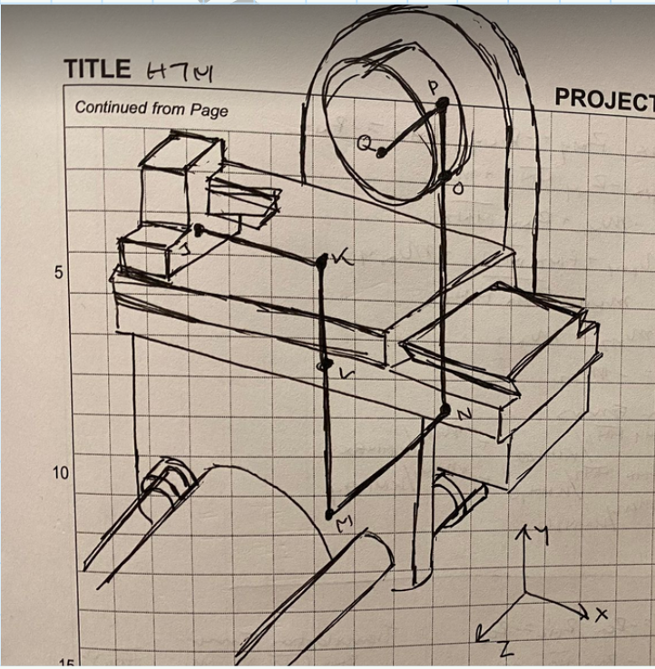
Homogenous Transfer Matrix (HTM) Model
To estimate how much error we expect our lathe to have, I created an HTM Model of the stiffness and deflection of the entire lathe. By approximating and measuring the stiffness of each component in the lathe, I calculated the total deflection of a part in the spindle under cutting forces. This informed us if a specific part was not stiff enough. We discovered that our tool holder contributed significantly to our lathe’s total error. We then modified the tool holder’s design to increase its stiffness and thus, decrease our lathe’s total error.
Competition and Wrap Up
When we finished our lathe, we used a Coordinate Measuring Machine (CMM) to measure it and check if it met our functional requirements. We found that the lathe did meet all functional requirements as seen below.
| Functional Requirement | Measured Value |
|---|---|
| MRR - 0.5 in3/min (0.02-0.6in3/min) | 0.24 in3/min |
| Max Cutting Force - 70 N (0 - 140 N) | Max 118 N |
| Spindle Speed - 1300 rpm (1000 - 1300 rpm) | 1050 rpm |
| Workable Part Diameter - 0.125" < 1" < 2" | Max 2" OD |
| Workable Part Length - 0.1" - 3.5" | Max 3.5" length |
| Repeatability - Max 50 microns | < 25 microns in Z and < 25 microns in X |
| Accuracy (no functional requirement) | 25 microns |
| Input Actuation - 0.25 Nm - 1 Nm | 0.24 ± 0.03 Nm |
| Max Temperature Fluctuation - Max 0.02 C/s | 0.015 ± 2 C/s |
| Overall Efficiency - 53% - 65% | At least 62% |
| Size - Max 2'x 4' x 1.5' | < 19" x 8" x 12" |
| Weight - 30 lbs - 60 lbs | 36.3 ± 0.1 lbs |
| Stiffness - X,Y > 6×10⁵ N/m and Z > 4×10⁵ N/m | X - 4.84×10⁵ ± 1.37×10⁵ N/m Y - 3.77×10⁶ ± 1.69×10⁶ N/m Z - 2.65×10⁶ ± 1.70×10⁶ N/m |
| External Force - Min 250 N | > 250 N |
We then participated in a class competition to test the MRR and accuracy of our lathes turning aluminum. We came in 3rd place in the MRR race with an MRR of 0.00975 in3/s and 2nd place in the accuracy race with an error of 0.00124” out of six teams.
Finally, our lathe experienced a drop test and sledgehammer test to test its durability and ability to remain repeatable within 50 microns. It was dropped approximately 1 m from the ground and the spindle was hit axially with a sledgehammer. Our lathe passed both these tests.
Learnings
This class was a great learning experience making precision machines. I learned the importance of establishing and validating functional requirements with calculations and measurements. I also developed a range of analytical skills like calculating design tradeoffs between lifetime, efficiency, compliance, and strength and creating HTM models to adjust design parameters. Finally, I practiced important engineering skills like precision machining, formulating process plans, and communicating.