LOHC Powertrain for LNK Energies
I connected with Sayandeep Biswas, a researcher in the MIT Green Research Group, to build a powertrain system for his Hydrogen Release Unit (HRU).
The Motivation
Heavy-duty trucks have a disproportionally high impact on energy use and emissions despite constituting only 5% of the entire vehicle inventory in the U.S. Existing sustainable technologies simply do not meet the low-margin needs of the industry today.
In the Green Research Group, Sayandeep researched the use of Liquid Organic Hydrogen Carriers (LOHCs) to decarbonize heavy-duty trucks. LOHCs are liquids that can safely store hydrogen in their chemical bonds. The LOHC molecule we are using is Benzyltoluene (BT). BT is non-flammable and compatible with existing diesel fuel infrastructure including pipelines, tanker trailers, gas stations, and pumps. This makes it extremely practical and cheap to scale. Sayandeep developed a Hydrogen Release Unit (HRU) that can efficiently extract hydrogen from LOHC unlocking its use an an alternative fuel for mobility. My role was to integrate our lab-scale HRU into a powertrain system.
Hydrogen Engine Research
We decided to integrate the HRU with an internal combustion engine to utilize the engine's exhaust heat for powering the HRU. We anticipated that this would improve the overall system efficiency by ~30%. Since we could not buy a commercial hydrogen combustion engine, we decided to retrofit a gasoline engine to run on hydrogen. I looked at research papers to understand the key differences between a hydrogen and gasoline engine, the process for retrofitting an engine, and safety considerations for dealing with hydrogen systems.I found that there are different types of hydrogen combustion engines depending on their fuel injection and ignition strategies.
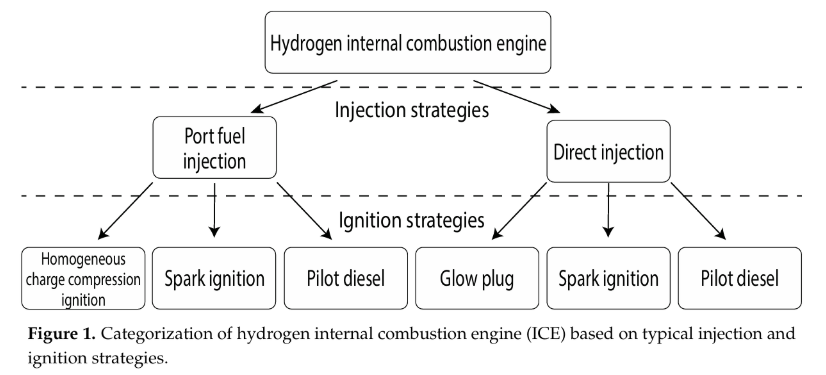
Port Fuel Injection (PFI) engines inject hydrogen gas in the intake valve and fuel is typically released in the intake cycle. The fuel can be stored at a lower pressure (40-60 psi) and there can be a better dispersion of fuel in the air. However, because of hydrogen’s short quenching distance and high laminar flame speed in air, these engines have a higher propensity for backfiring. In addition, the fuel can become hot before entering the chamber leading to knock.
Direct Injection (DI) engines inject hdyrogen gas directly into the chamber typically during the compression cycle. The fuel must be stored at a higher pressure (~100+ psi) and DI engines can have a higher compression ratio leading to better performance and higher efficiency. In addition, fuel can be injected cold which makes it less likely to knock. However, there is the potential for low-speed pre-ignition and less dispersion of fuel in the air.
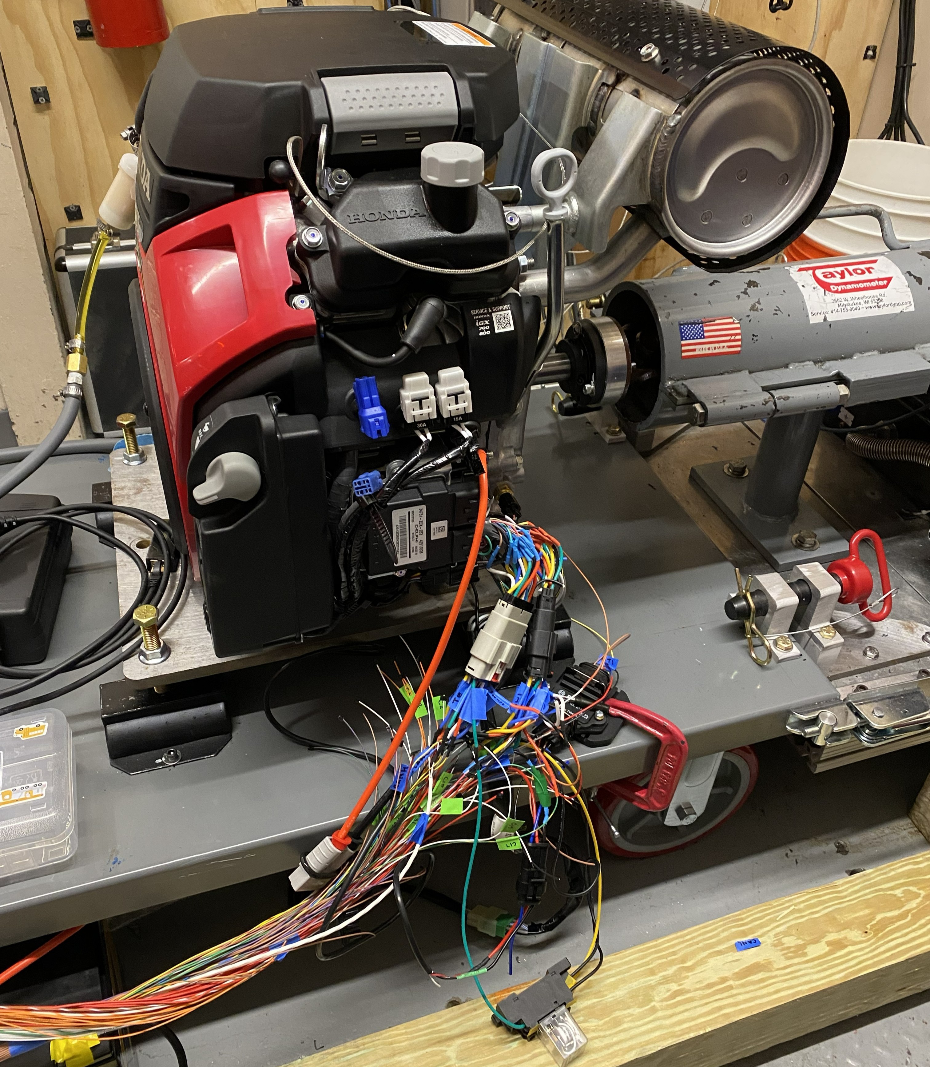
I decided to go with a PFI engine since the fuel injection pressure matched the output hydrogen pressure of the HRU. Next, I needed to decide between a carburetor and electronic PFI system. The carburetor is a cheaper and simpler system. However, I would not have any control over the injection parameters; therefore, I decided to go with an electronic PFI system. Finally, I wanted to match the power rating of the HRU (~12 kW). With these requirements, I bought a Honda iGX700 engine.
Retrofitting Process
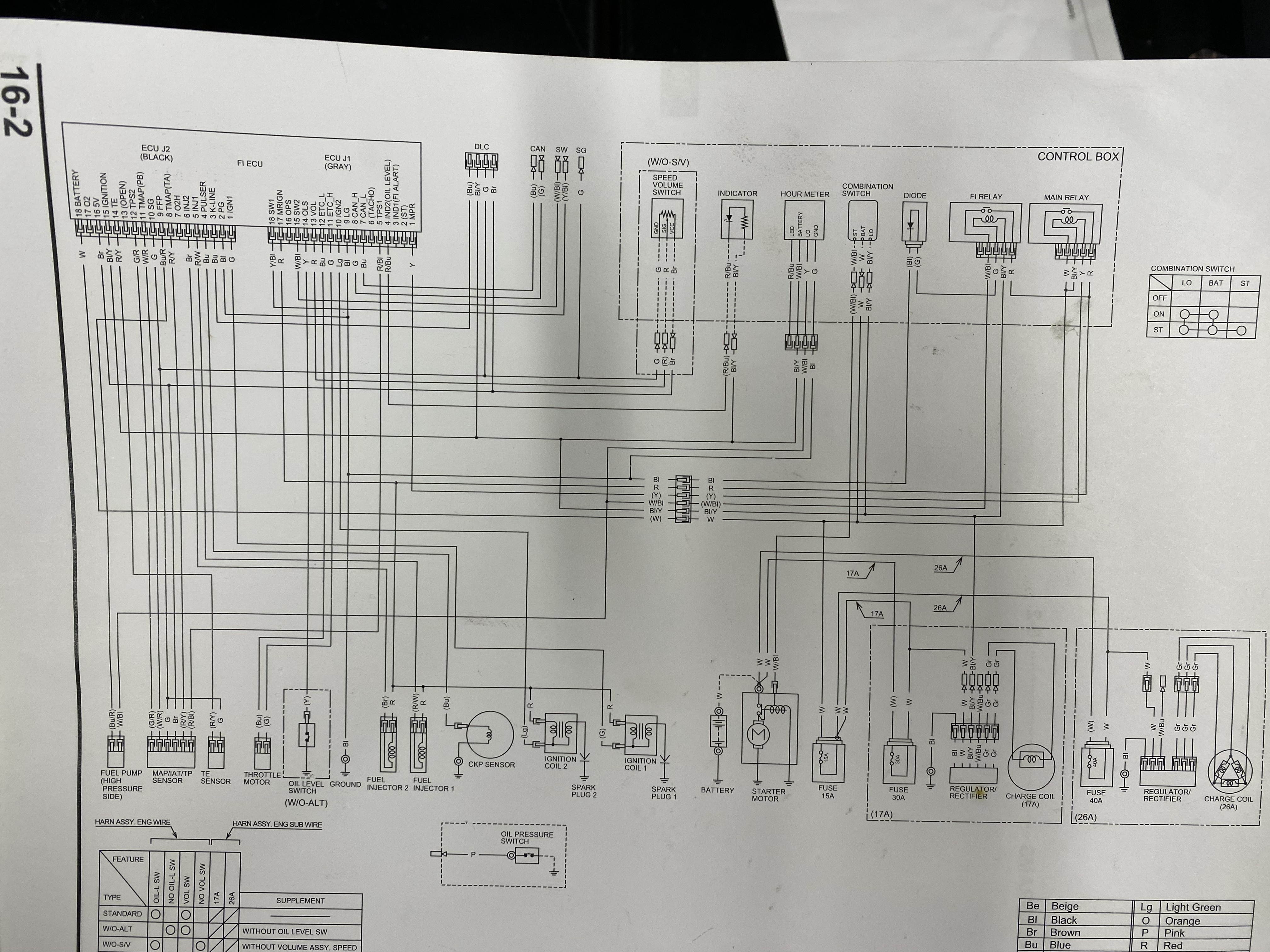
1. Replace OEM ECU with a programmable ECU
I replaced the engine’s ECU with an aftermarket programmable ECU (Motec M150) to adjust the engine parameters for hydrogen fuel. Since I did not receive OEM support for this retrofit, I had very little documentation I could use. This was the only schematic in the engine service manual.
I wanted to be able to easily switch between the new and OEM ECU. However, because I didn’t know which connector the OEM ECU used, I had to put in my own connector in between the ECU and the rest of the engine wires. I also had to figure out how to power / operate all of the existing sensors, fuel injectors, and ignition coils on the engine with my new ECU. I had Motec test the fuel injectors and ignition coils. For the manifold air pressure (MAP) sensor and temperature sensor, I bought a Dr.H diagnostic tool kit to read the sensor data while I ran the engine. The MAP sensor had a lot of noise so I replaced it with a different MAP sensor which required new mounting. I also replaced the fuel pressure sensor.
Once everything was wired to the new ECU, I ran the engine with gasoline to make sure all of the changes I made worked.
Now, I started working on making the engine compatble with hydrogen.
2. Replace spark plugs
I replaced the engine’s OEM spark plugs with a non-platinum cold-rated spark plug. This helps to avoid pre-ignition and backfiring in spark-ignited engines. Platinum material in the spark plug can have an undesirable catalytic response with hydrogen and air. Therefore, cold-rated spark plugs can facilitate quick heat transfer to minimize hydrogen exposure to hot spots that lead to engine knock and abnormal combustion.
3. Replace Fuel Injectors
The engine’s OEM fuel injectors were originally made for gasoline fuel. Therefore, they would not be compatible with gaseous fuels that have less lubricative properties. Since there were no hydrogen fuel injectors commercially available, I used CNG injectors since they were the closest gaseous fuel injectors I could buy. I made sure to size the CNG injectors for the amount of hydrogen I will be injecting.
A problem I ran into was finding the fuel injector’s latency characteristics. It was not available from the part supplier, and Motec could not do it since their testing rig was not set up for hydrogen gas. Fuel injector latency is the lag in time it takes for the fuel injectors to open from when they are initially powered. This is an important parameter for ensuring accurate fuel injection timing. Finding these paramters was surprisingly simple. I connected a power supply to the fuel injectors and supplied it with helium. I measured the voltage and current draw from the fuel injectors with an oscilloscope. I could tell when the fuel injector opened by the spike in current draw. I measured the distance from when the voltage was supplied to this spike in current to find the latency time. I varied the power supply voltage from 8-14V and the helium fuel pressure from 15-50 psi and found the latency for each of these conditions.
Next, I designed and manufactured a new mounting system for the fuel injectors. I did not want to make any changes to the original injector mounts so I designed an adapter piece in between the original mount and new fuel injectors. Since hydrogen is the easiest fuel to leak, I calculated the necessary diameter and groove depth to achieve the appropriate o-ring compression for hydrogen sealing.
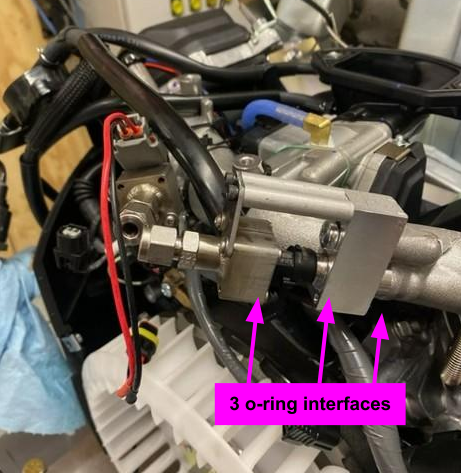
And it worked the first time! The hydrogen leak rate from the fuel injector mounts at ~50 psi was less than 1 SLPH which was sufficient for our powertrain tests.
4. Misc. Test Set Up and Safety SOPs
We needed to be able to turn on and off the engine outside of the dyno room. I extended the engine’s control panel wiring so that I could access it outside of the room. To minimize hydrogen slip in the exhaust, we attached a hydrogen burner to the exhaust manifold. We also had extensive conversations with MIT EHS to ensure safe hydrogen operation. We made pre-flight checklists and SOPs to minimize human error when setting up and running the hydrogen error.
4. Engine Parameter Optimization
We had to adjust the engine’s parameters for hydrogen combustion. I had some support from Motec on how to optimize the engine map. Essentially, during engine idle, we tuned the feed forward parameters which controls how much extra fuel to inject during startup. Once the engine was warmed up, we tuned the engine efficiency map to minimize the fuel close loop control and bring the engine’s exhaust lambda as close as possible to the fuel mixture aim.
Once the engine could reliable run on hydrogen gas, I moved on to the next step: integrating it with our HRU.
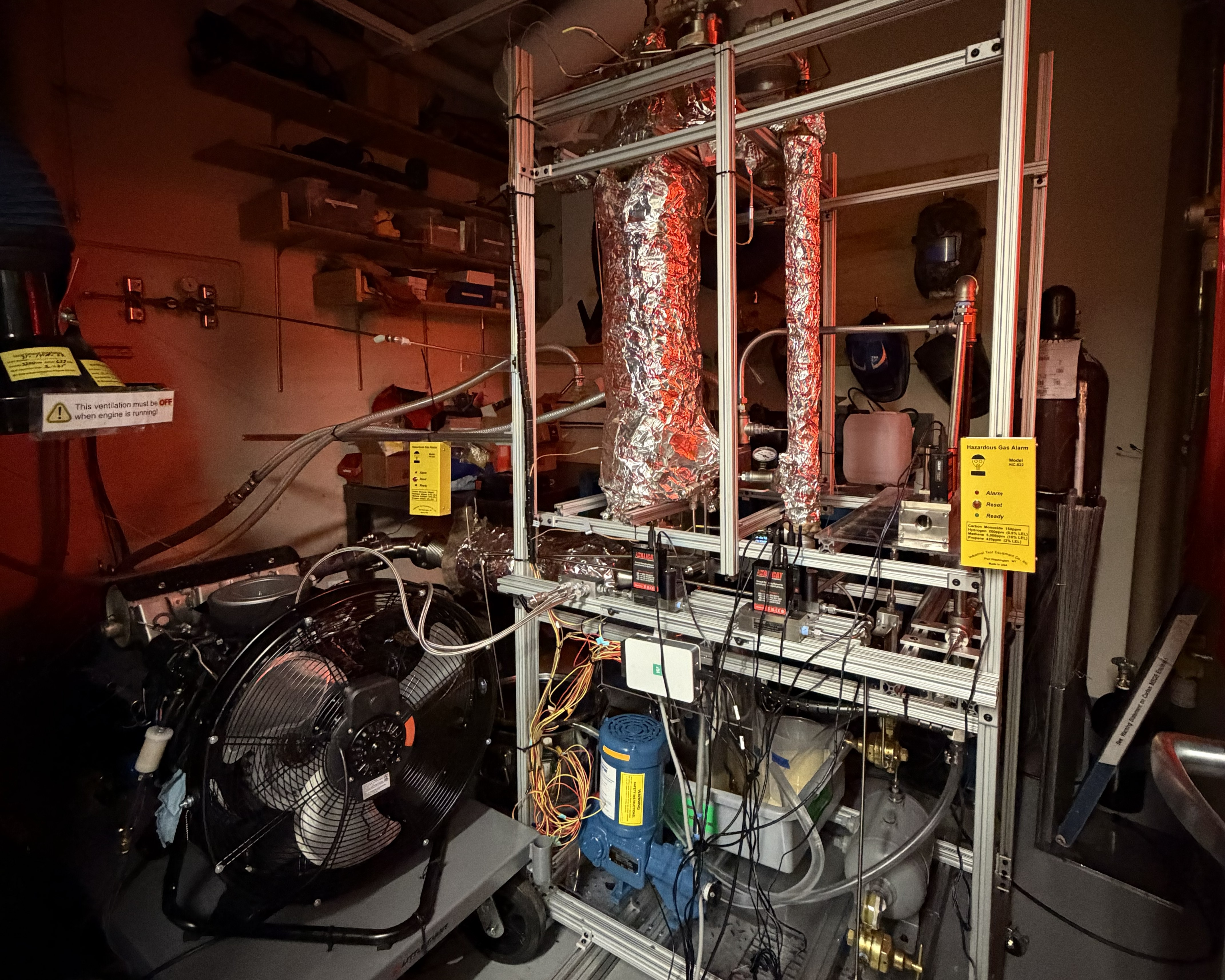
HRU Integration
I repackaged the HRU so that it would be more compact, portable, and fit inside the dyno room.
I then connected the engine’s exhaust to the HRU and the HRU’s hydrogen output to the engine’s fuel injectors.
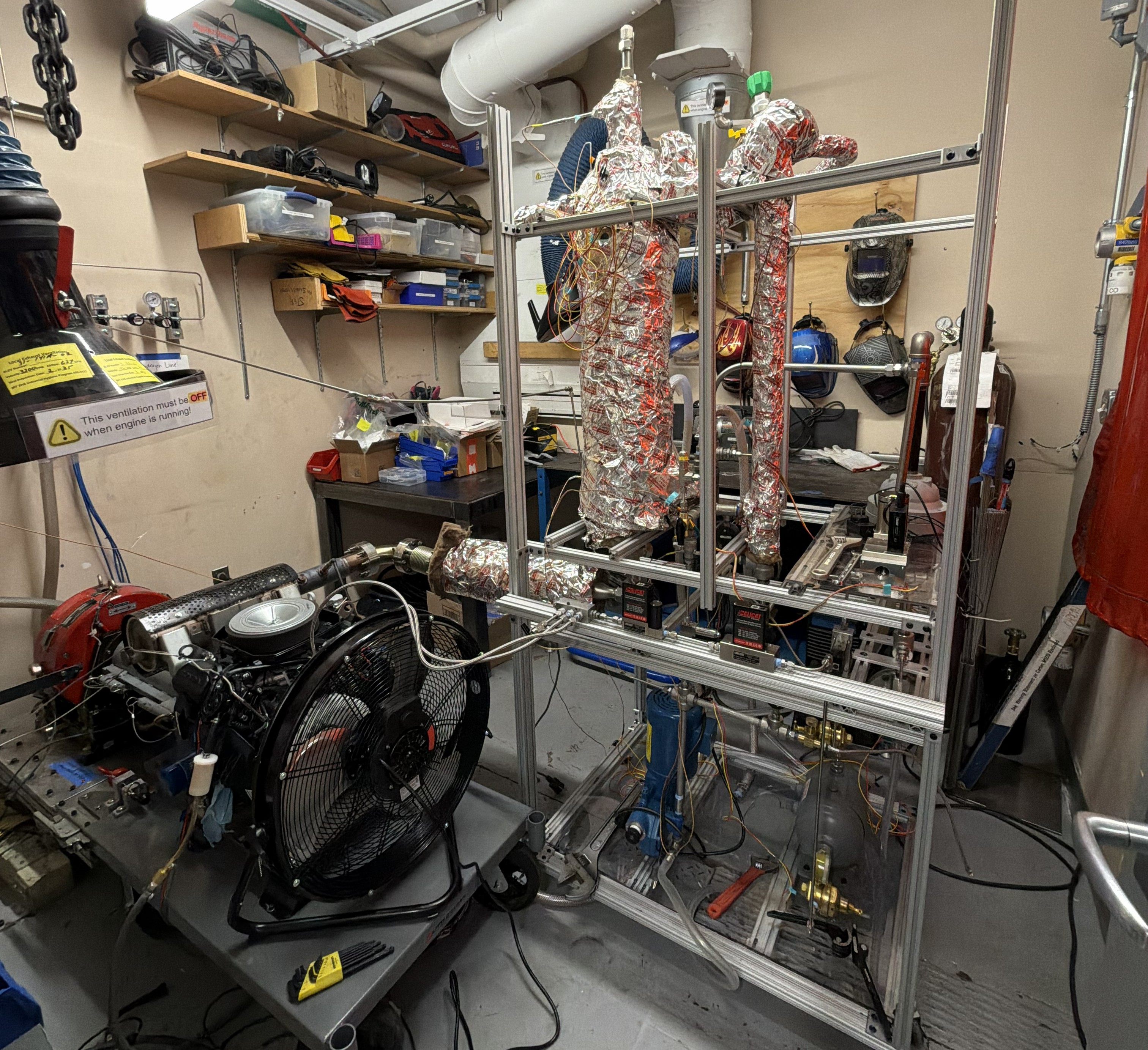
We successfully ran the engine for 6+ hours on the hydrogen produced by the HRU and LOHC fuel.